Run
Configure your settings using Terraform and Ansible.
Run using Terraform
In this activity you will:
- Initialize the Provider
- Configure Network Interfaces
- Configure Virtual Router
- Configure Security Zones
For this portion of the lab, you will be using the Palo Alto Networks Terraform for PAN-OS provider.
First, change to the Terraform configuration directory.
cd ~/utd-automation/journey/configuration/terraform
Provider Initialization
Your first task is to set up the communications between the provider and your
lab firewall. There’s several ways this can be done. The IP address,
username, and password (or API key) can be set as variables in Terraform, and
can be typed in manually each time the Terraform plan is run, or specified on
the command line using the -var command line option to terraform plan
and terraform apply. You can also reference a JSON file in the provider
configuration which can contain the configuration.
Another way you can accomplish this is by using environment variables. Use the following commands to add the appropriate environment variables:
export PANOS_USERNAME="admin"
export PANOS_PASSWORD="PaloAlto2005"
export PANOS_HOSTNAME="<YOUR FIREWALL MGMT IP GOES HERE>"
Note
Replace the text <YOUR FIREWALL MGMT IP GOES HERE> with your firewall’s management IP address.
Now, you should see the variables exported in your shell, which you can verify
using the env | grep PANOS command:
PANOS_USERNAME=admin
PANOS_PASSWORD=PaloAlto2005
PANOS_HOSTNAME=54.160.48.152
With these values defined, we can now initialize the Terraform panos provider with the following command.
terraform init
The provider is now ready to communicate with our firewall.
Confirm firewall readiness (optionnal)
Now the firewall should be up and running, you can SSH into the firewall with the following credentials:
- Username:
admin - Password:
PaloAlto2005
ssh admin@
Enter the IP address of the firewall management
interface that was provided in the Terraform plan results. This information
can be easily recalled using the terraform output command within the
deployment directory.
Warning
If you are unsuccessful the firewall instance is likely still
bootstrapping or performing an autocommit. Hit Ctrl-C and try again
after waiting a few minutes. The bootstrap process can take up to ten
minutes to complete before you are able to successfully log in.
Once you have logged into the firewall you can check to ensure the management plane has completed its initialization.
admin@lab-fw> show chassis-ready
If the response is yes, you are ready to proceed with the configuration
activities.
Note
While it is a security best practice to use SSH keys to authenticate to VM instances in the cloud, we have defined a static password for the firewall’s admin account in this lab (specifically, in the bootstrap package). This is because the PAN-OS XML API cannot utilize SSH keys and requires a username/password or API key for authentication.
Network Interfaces
Your firewall has been bootstrapped with an initial password and nothing else. We’re going to be performing the initial networking configuration with Terraform.
You’ve been provided with the following Terraform plan in main.tf:
provider "panos" {}

resource "panos_ethernet_interface" "untrust" {
  name                      = "ethernet1/1"
  comment                   = "untrust interface"
  vsys                      = "vsys1"
  mode                      = "layer3"
  enable_dhcp               = true
  create_dhcp_default_route = true
}

resource "panos_ethernet_interface" "web" {
  name        = "ethernet1/2"
  comment     = "web interface"
  vsys        = "vsys1"
  mode        = "layer3"
  enable_dhcp = true
}

resource "panos_ethernet_interface" "db" {
  name        = "ethernet1/3"
  comment     = "database interface"
  vsys        = "vsys1"
  mode        = "layer3"
  enable_dhcp = true
}
This configuration creates your network interfaces. The PAN-OS provider doesn’t need any additional configuration specified because it is pulling that information from the environment variables we set earlier.
Now, you can run the terraform apply command, and the interfaces will be created on the
firewall.
terraform apply
Virtual Router
Now, you’ll have to assign those interfaces to the default virtual router. You will need the panos_virtual_router resource.
The example code from that page looks like this:
resource "panos_virtual_router" "example" {
    name = "my virtual router"
    static_dist = 15
    interfaces = ["ethernet1/1", "ethernet1/2"]
}
Exercise:
Open VS Code and edit the main.tf file to add a code snippet that will add a virtual router to your configuration, matchning the following settings:
code main.tf
# or
subl main.tf
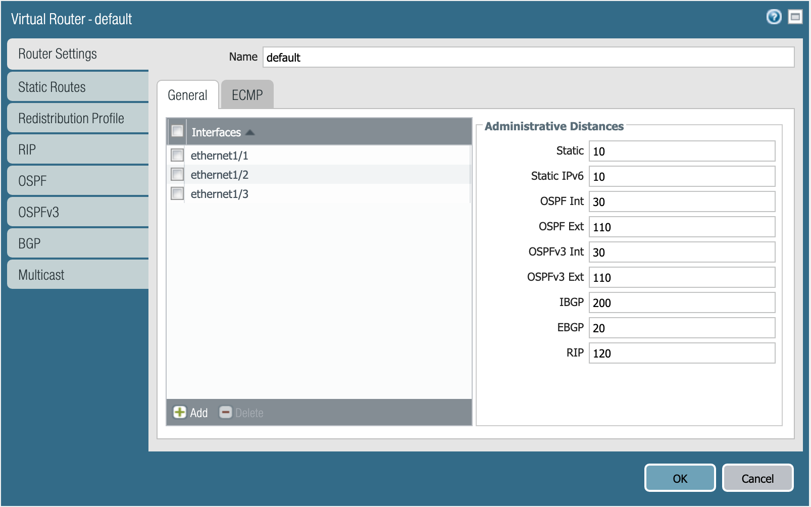
Virtual router default. :align: center
Once the virtual router resource in main.tf has been added and the file saved (CTRL+S) you can run terraform apply.
terraform apply
Note
When a value is by default, you do not need to specify it in your Terraform file. The Static Distance is 10 by default.
Security Zones
Next is creating the security zones for the firewall. You will need the panos_zone resource.
The example code from that page looks like this:
resource "panos_zone" "example" {
    name = "myZone"
    mode = "layer3"
    interfaces = ["${panos_ethernet_interface.e1.name}", "${panos_ethernet_interface.e5.name}"]
    enable_user_id = true
    exclude_acls = ["192.168.0.0/16"]
}

resource "panos_ethernet_interface" "e1" {
    name = "ethernet1/1"
    mode = "layer3"
}

resource "panos_ethernet_interface" "e5" {
    name = "ethernet1/5"
    mode = "layer3"
}
Exercise:
Open VS Code and edit the main.tf file to add a code snippet that will add three zones mapped with the right interfaces to your configuration, matchning the following settings:
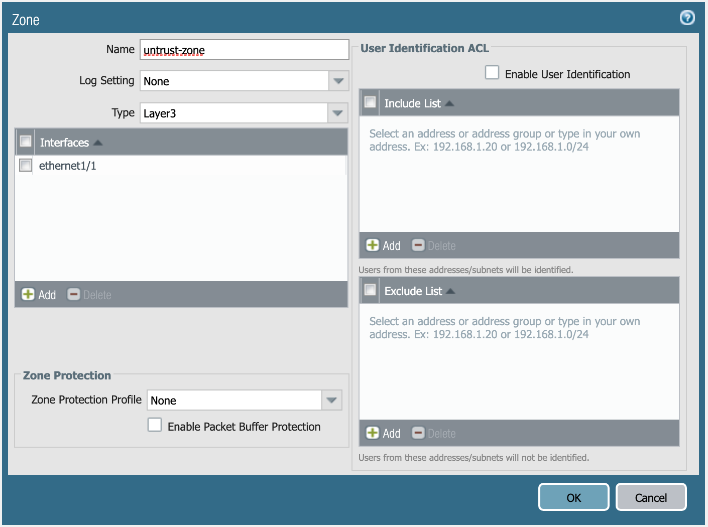
Definition of untrust-zone. :align: center
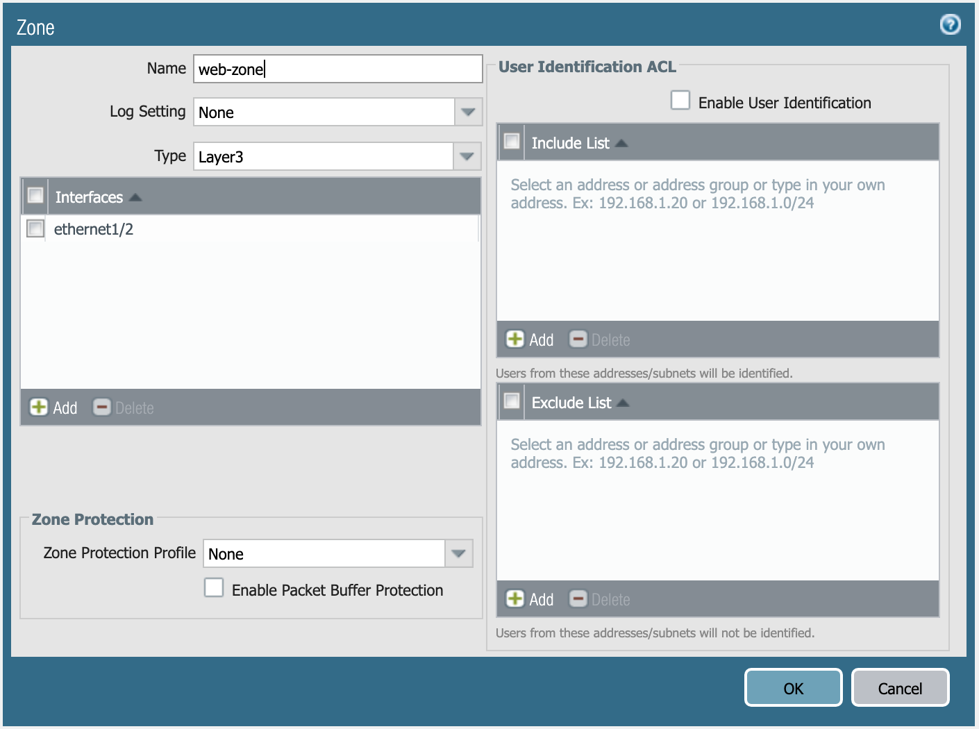
Definition of web-zone. :align: center

Definition of db-zone. :align: center
Once the zones and mapping in main.tf have been added and the file saved (CTRL+S) you can run terraform apply.
terraform apply
You’re done with the Terraform portion of the lab!
Run using Ansible
In this activity you will:
- Define Module Communications
- Define Address Objects
- Define Service Objects
- Define Security Rules
- Define NAT Rules
- Commit the Configuration
- Run the Playbook
For this portion of the lab, you’re going to be using the Palo Alto Networks Ansible modules.
First, let’s change to the Ansible configuration directory.
cd ~/utd-automation/journey/configuration/ansible
Module Communications
The vars.yml file contains the following:
provider:
  ip_address: "{{ lookup('env', 'PANOS_HOSTNAME') }}"
  username: "{{ lookup('env', 'PANOS_USERNAME') }}"
  password: "{{ lookup('env', 'PANOS_PASSWORD') }}"
This code simply reads the content of the environment variables (env | grep PANOS) we set in the
Terraform portion into the dictionary provider. This is then referenced by
our playbook file, playbook.yml.
Similar to the Terraform portion of the lab, our firewall doesn’t have any objects or rules configured. We’re going to implement that with an Ansible playbook.
Note
You wouldn’t actually change tools in the middle of configuration like we’re doing here. We just want you to get exposure to both tools and see that you can accomplish the same tasks with either one.
Address Objects
Open the playbook.yml file in your text editor.
code playbook.yml
# or
subl playbook.yml
It will contain the following:
---
- hosts: localhost
  connection: local
  gather_facts: false

vars_files:
  - vars.yml

collections:
  - paloaltonetworks.panos

tasks:
  - name: Create web server object
    panos_address_object:
      provider: "{{ provider }}"
      name: "web-srv"
      value: "10.5.2.5"
      commit: False
      state: present

  - name: Create DB server object
    panos_address_object:
      provider: "{{ provider }}"
      name: "db-srv"
      value: "10.5.3.5"
      commit: False
      state: present
This playbook creates the following address objects by using the
panos_address_object module.
Also notice the fact that commit is set to False, so that we don’t have
to wait on a commit each time a module runs.
Service Objects
Next, create some service objects. We want to allow SSH on some non-standard ports so we can easily communicate with web and DB servers behind our firewall. You’ll need to refer to the panos_service_object module documentation.
The example code for that module looks like this:
- name: Create service object 'ssh-tcp-22'
  panos_service_object:
    provider: '{{ provider }}'
    name: 'ssh-tcp-22'
    destination_port: '22'
    description: 'SSH on tcp/22'
Exercise:
Use the panos_service_object module to create two objects with the
following definitions:
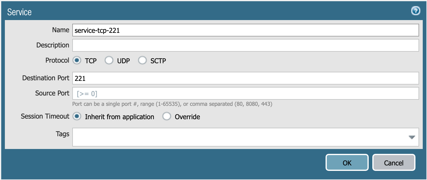
service-tcp-221 service object.
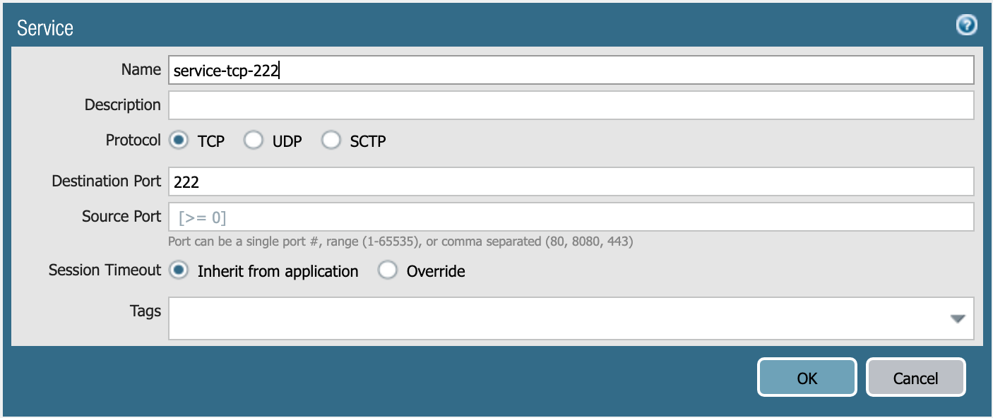
service-tcp-222 service object.
Security Rules
Now we need to create security rules to allow traffic. You’ll need to refer to the panos_security_rule module documentation.
The example code for that module looks like this:
- name: add SSH inbound
  panos_security_rule:
    provider: '{{ provider }}'
    rule_name: 'SSH permit'
    description: 'SSH rule test'
    source_zone: ['public']
    source_ip: ['any']
    destination_zone: ['private']
    destination_ip: ['1.1.1.1']
    application: ['ssh']
    action: 'allow'
Exercise:
Use the panos_security_rule module to create the following security rules:
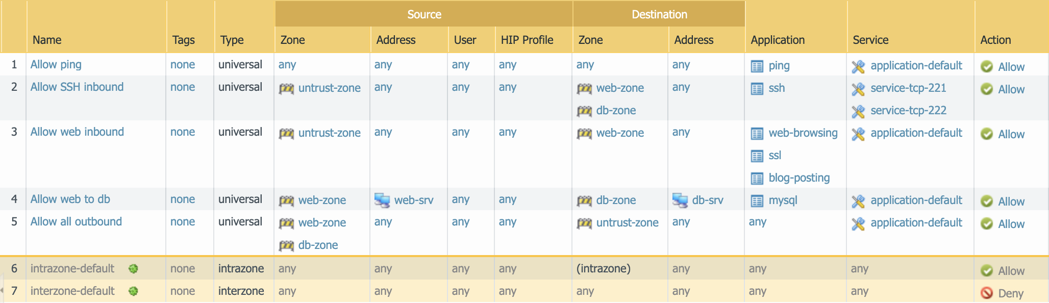
Security rules to be created.
NAT Rules
Now we need to create the required NAT rules. You’ll need to refer to the panos_nat_rule module documentation.
The example code for that module looks like this:
- name: Create NAT SSH rule for 10.0.1.101
  panos_nat_rule:
    provider: '{{ provider }}'
    rule_name: "Web SSH"
    source_zone: ["external"]
    destination_zone: "external"
    source_ip: ["any"]
    destination_ip: ["10.0.0.100"]
    service: "service-tcp-221"
    snat_type: "dynamic-ip-and-port"
    snat_interface: "ethernet1/2"
    dnat_address: "10.0.1.101"
    dnat_port: "22"
Exercise:
Use the panos_nat_rule module to create the following NAT rules:
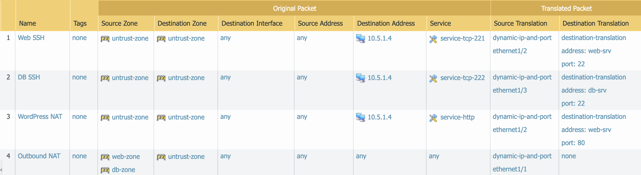
NAT rules to be created.
Note
Pay attention to the module arguments for panos_nat_rule. destination_zone
and service are strings here, not lists. This is because you can’t
write a NAT rule on PAN-OS with multiple destination zones or services.
Commit the Configuration
If you have been writing your playbook with commit set to False each
time, you have an uncommitted candidate configuration. There’s a panos_commit
module to perform a commit.
The example code for the module should do what you need, copy and paste the following snippet to your playbook.yml file:
- name: commit candidate config on firewall
  panos_commit_firewall:
    provider: '{{ provider }}'
Run the Playbook
Don’t forget to save your playbook.yml file. Then run your playbook with the
following command:
ansible-playbook -i inventory playbook.yml
Log in to the web UI of the firewall, and verify that the configuration matches what you want. If you get errors, indentation is most likely the problem. Ansible is very particular about lines being indented with spaces and not with tabs.
You’re now done with the Ansible portion of the lab!
Validation Testing
In this activity you will:
- Access the Apache web server
- Access the WordPress application
- Post a blog article
- Verify firewall rule matches
The previous two activities had you deploy and configure the infrastructure supporting our WordPress application. Now it’s time to see if everything works as planned. If so, you should be able to access the application, post a blog article, and verify that the appropriate firewall rules are being hit. If not, you will need to troubleshoot your configs and make the necessary corrections.
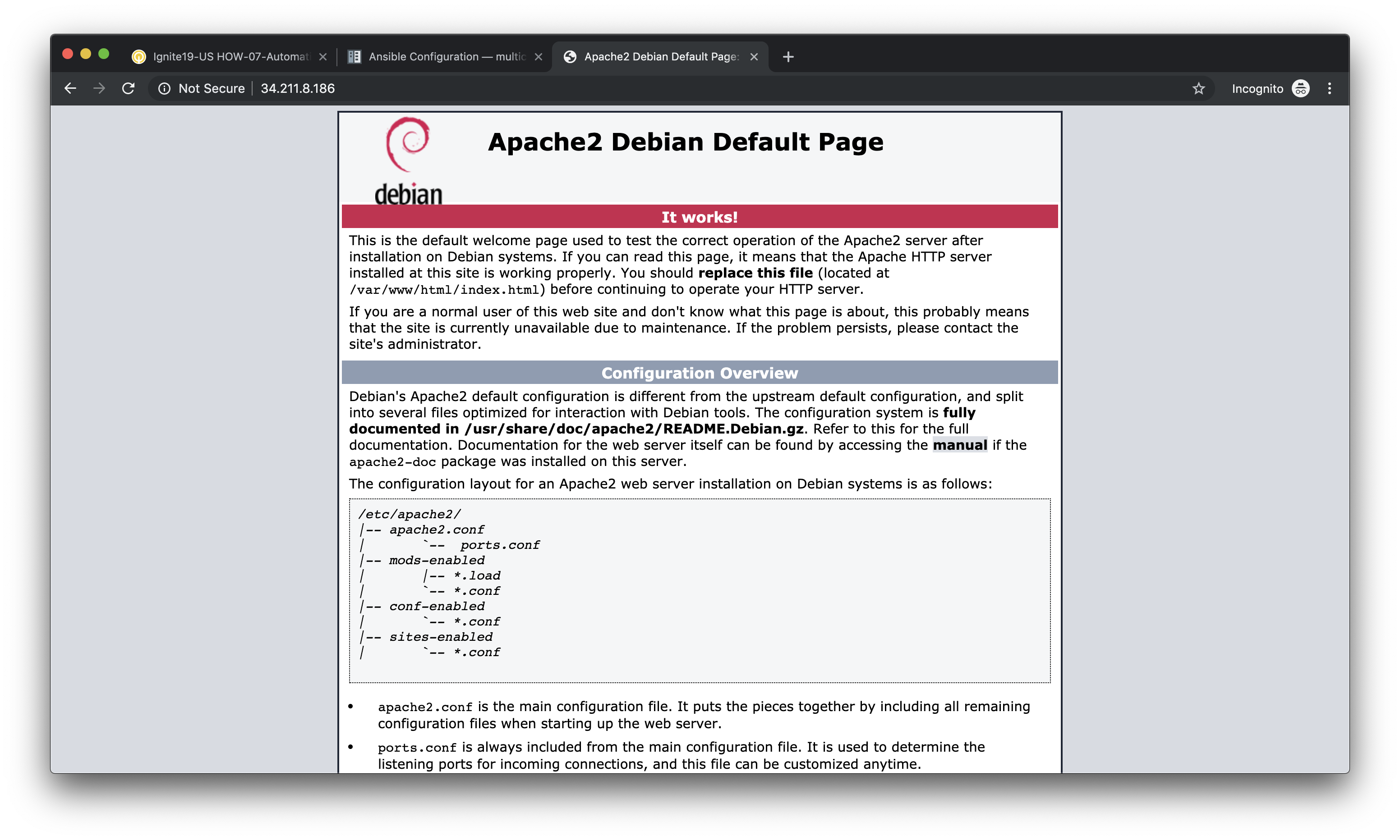
Access the Apache web server
The web server is using the firewall’s untrust interface address in a destination NAT rule. Run the following commands to determine the IP address of this interface.
cd ~/utd-automation/journey/deployment/aws
terraform output
Open a new tab in your web browser and go to http://<web-server-ip-address>.
You should see the Apache default home page.
Access the WordPress application
Append /wordpress to the end of the web server URL and the WordPress
installation page should be displayed.
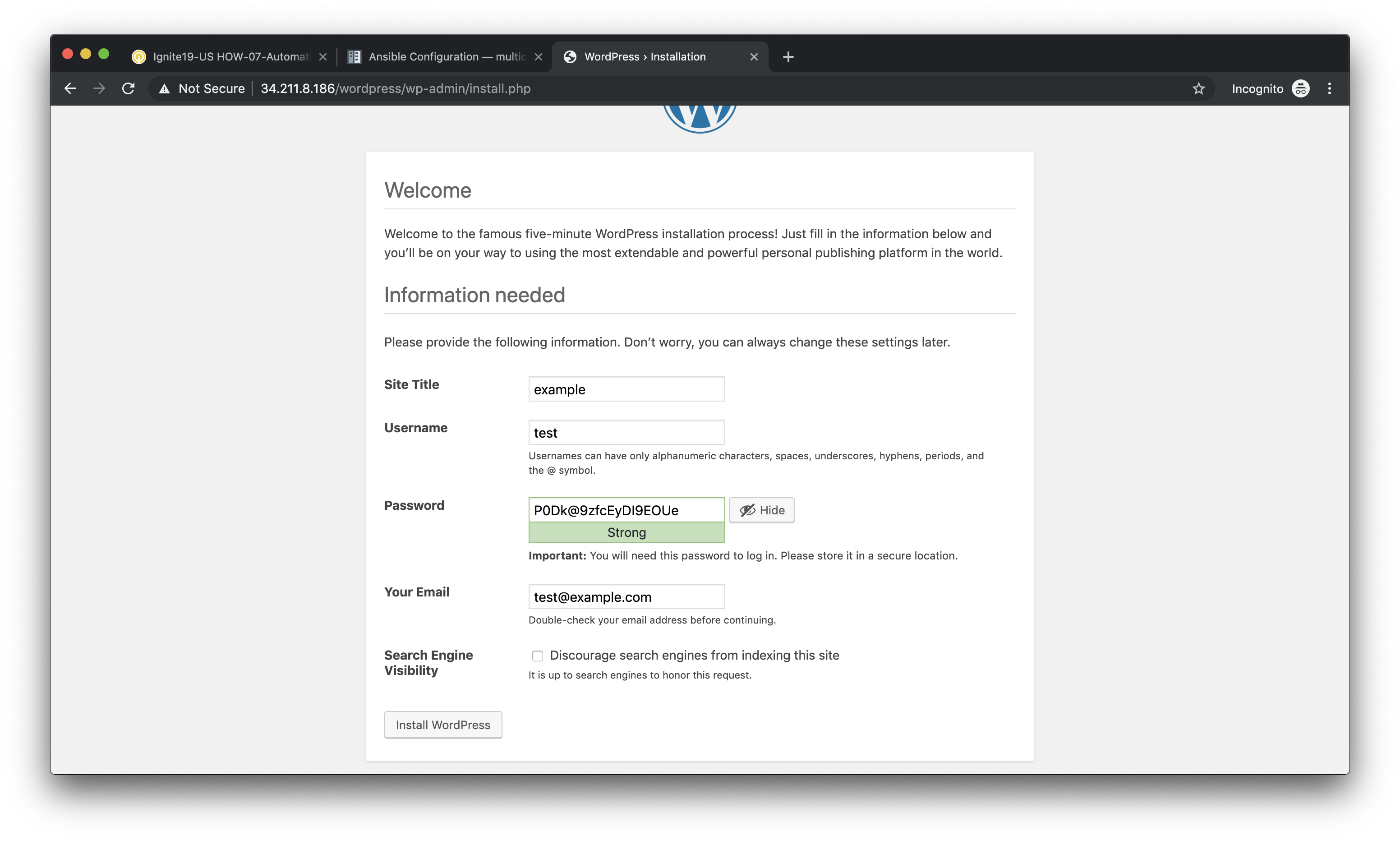
Fill in values of your choosing for the Site Name, Username, and Your Email. These are only for testing and do not need to be real values.
Note
Make sure you copy the password that is provided to your clipboard. Otherwise you may not be able to log in once WordPress is installed.
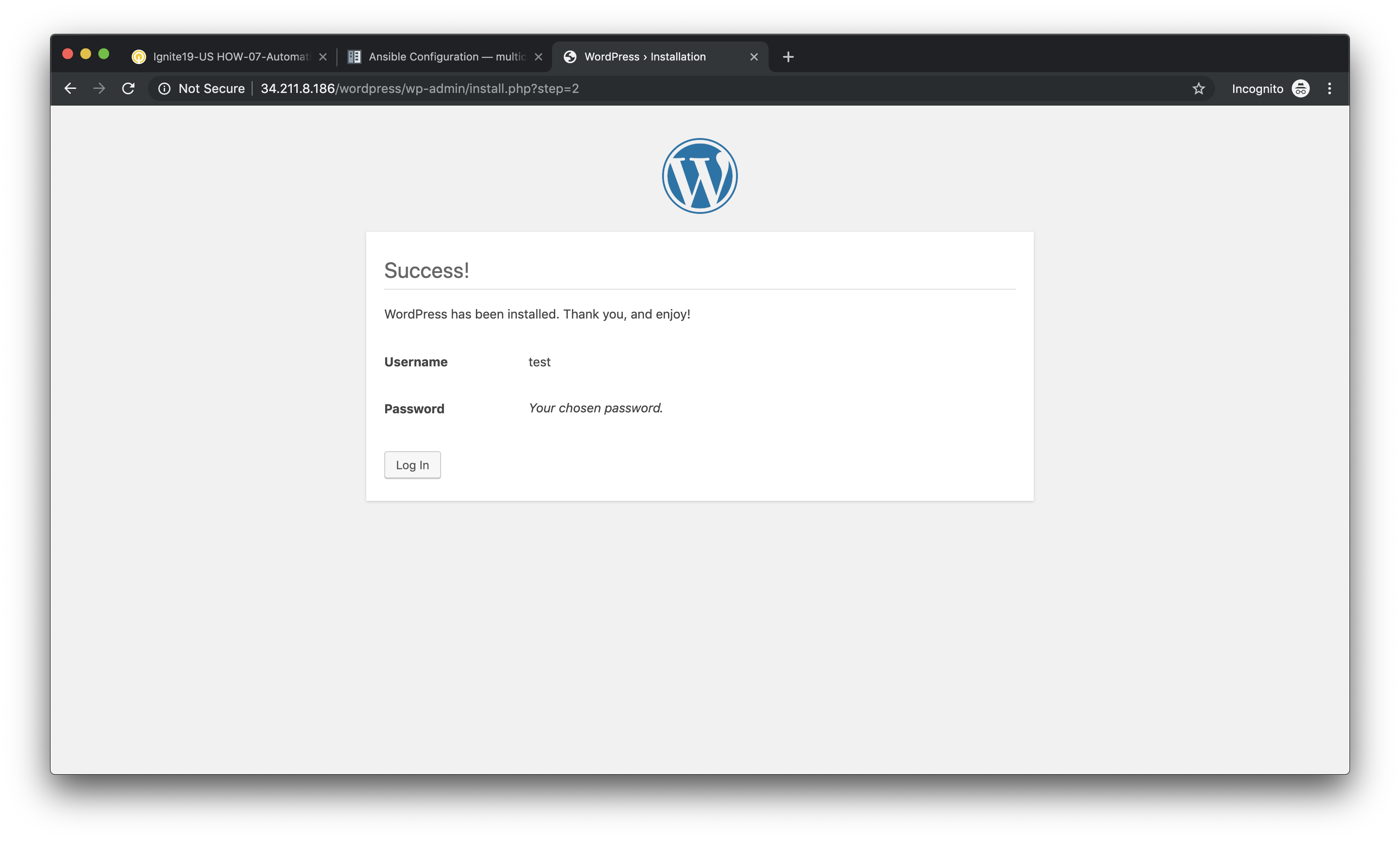
Click Install WordPress when you are done.
On the following page, click on Log In to log into the WordPress administrator dashboard.
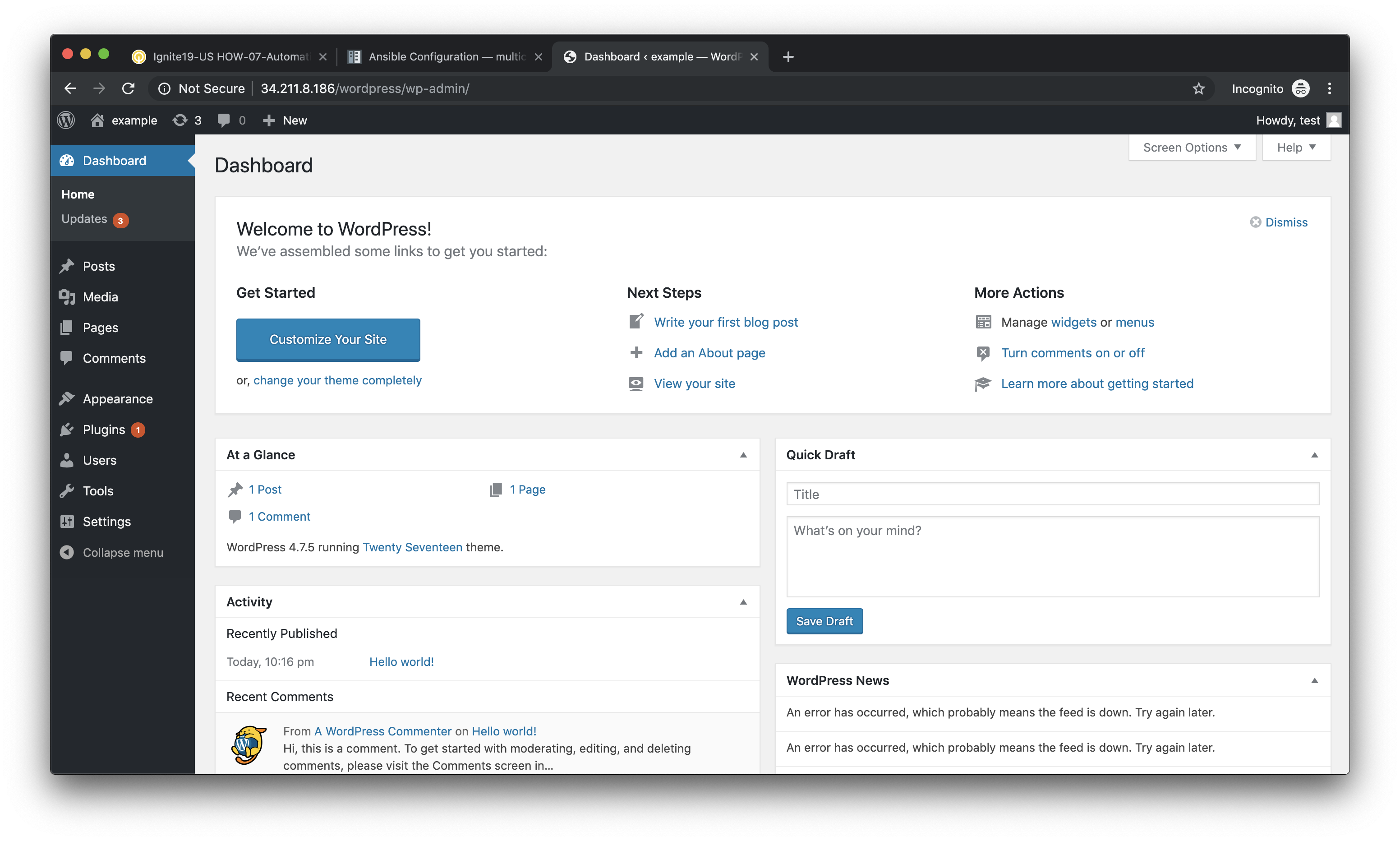
Log into WordPress using the username and password you created.

You will then be presented with the WordPress administrator dashboard.
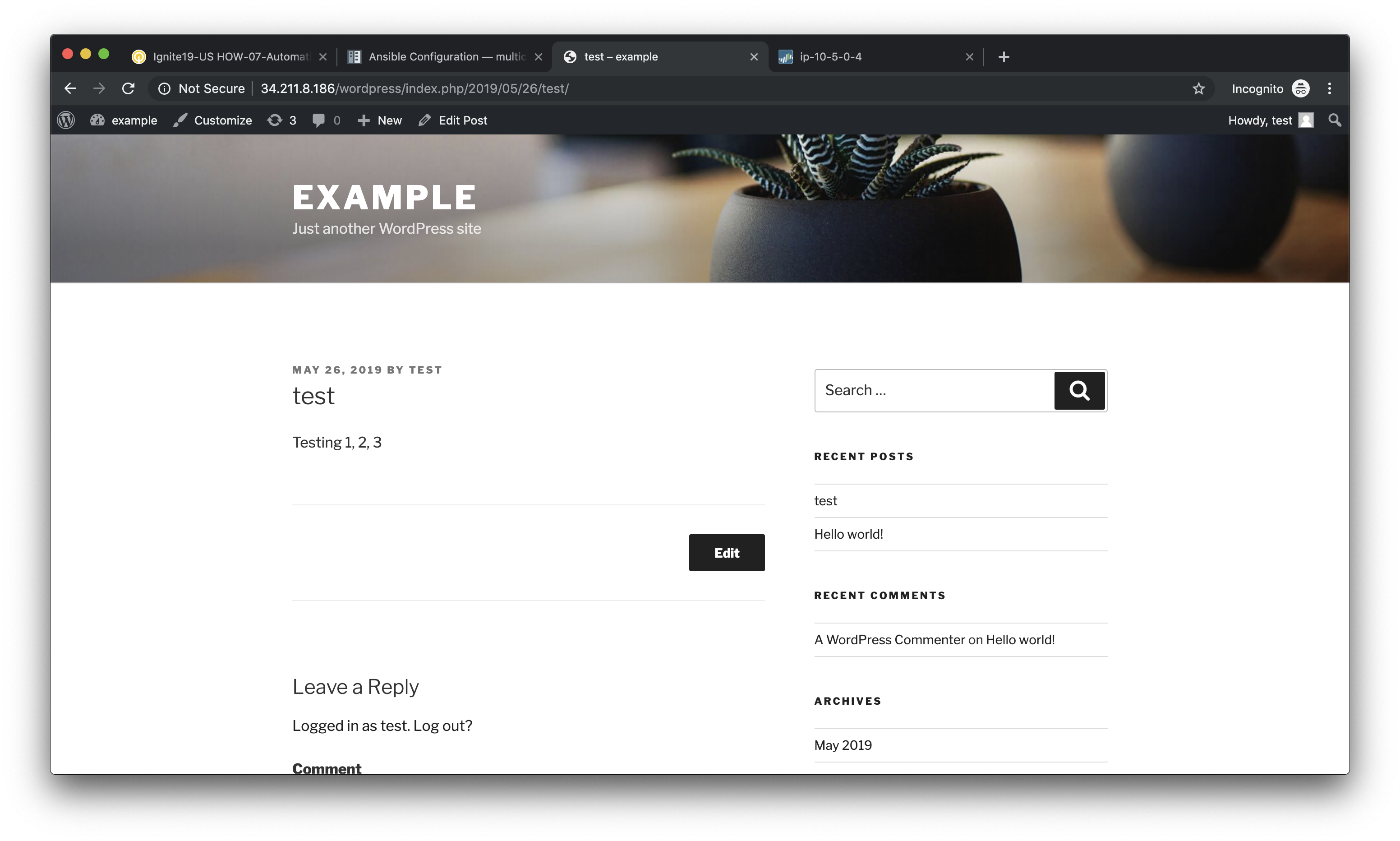
Post a blog article
Now that you’ve successfully logged into the WordPress administrator dashboard, let’s post an update to the blog.
Click on Write your first blog post under the Next Steps section. You will be presented with the Add New Post editor.
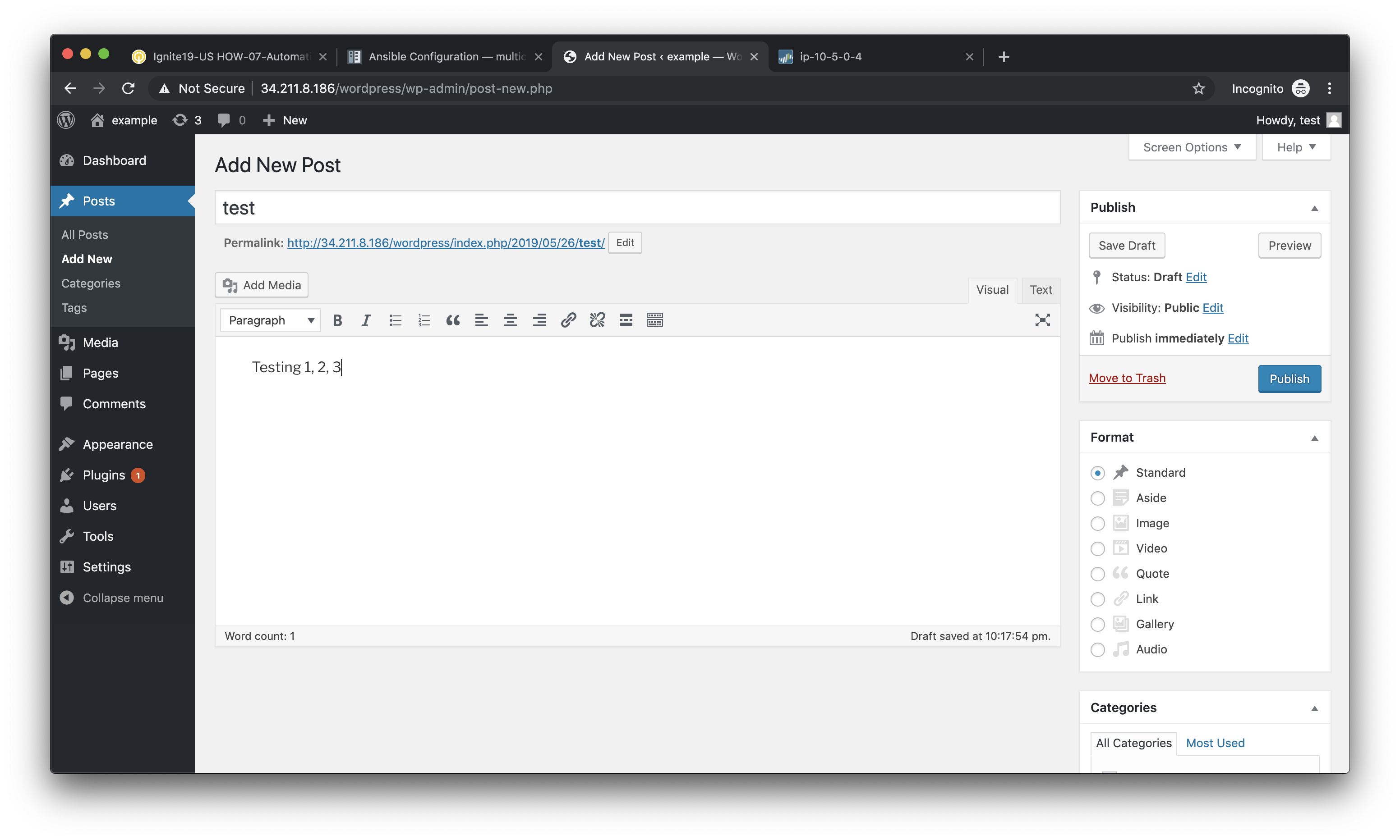
Enter a title for your post and some sample content. Then click on Publish to post the update.
You can then click on Preview to see the published blog update.
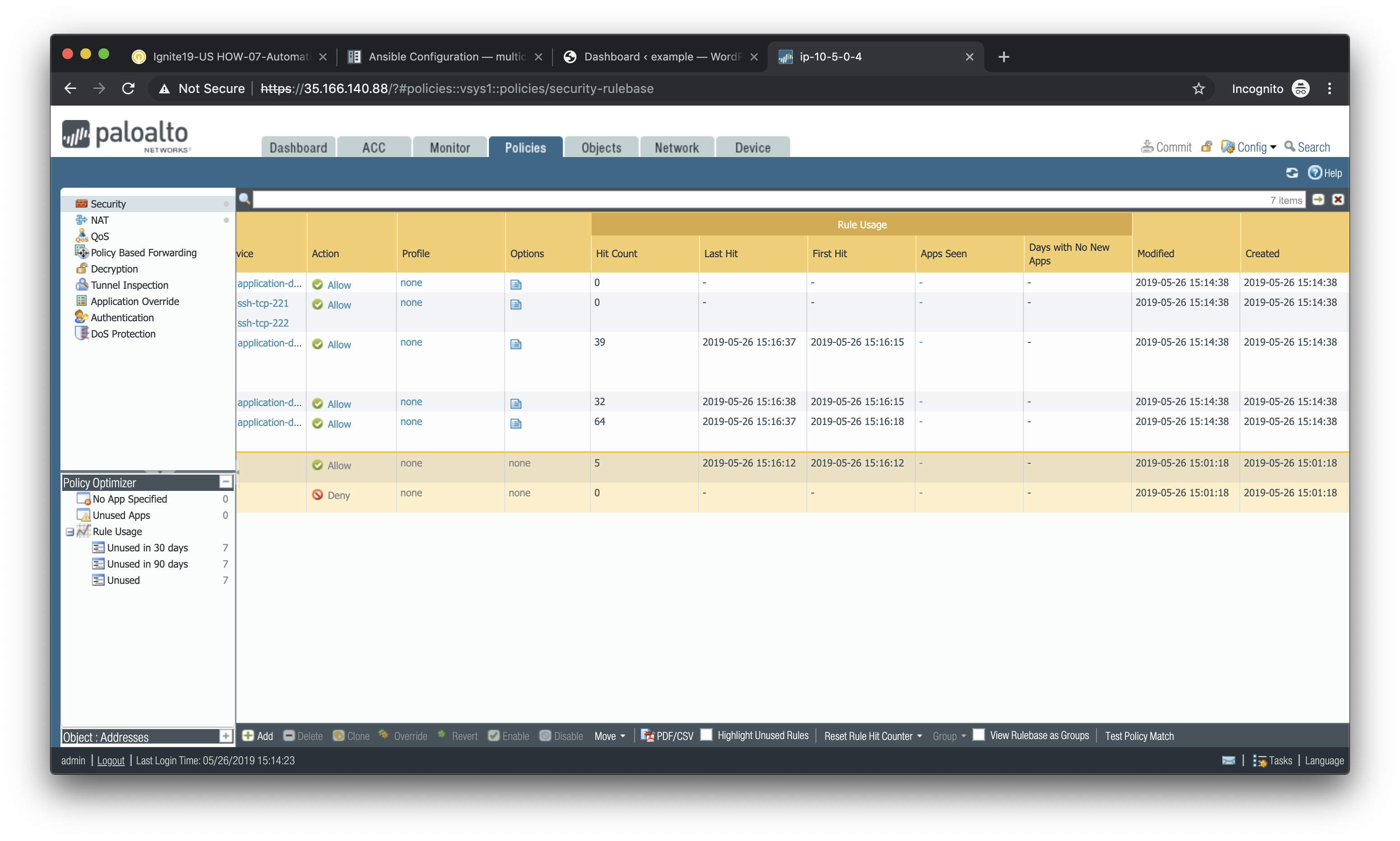
Verify firewall rule matches
Now that we’ve confirmed the WordPress application is working properly, let’s see what is happening with our firewall rules.
Log into the firewall administrator web interface at https://<firewall-management-ip>
and navigate to Policies > Security.
If you scroll to the right you will see details on the security rules that are being hit.
Scroll back to the left, find the security rule entitled Allow web inbound. Then click on the drop-down menu icon to the right of the rule name and select **Log Viewer*.
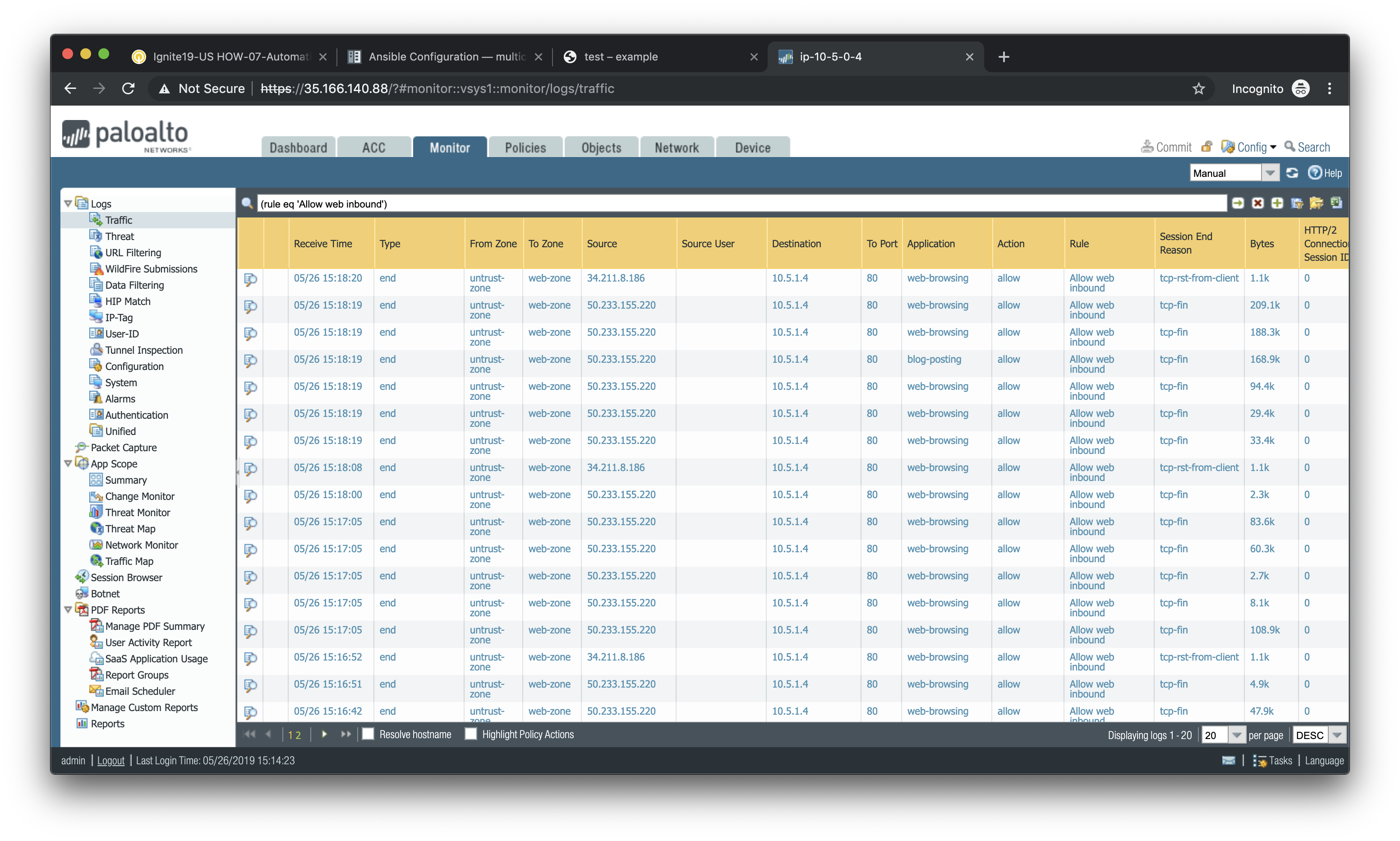
You will see all of the logs associated with inbound web traffic. Notice the applications identified are web-browsing and blog-posting.
Note
You may find source IPs other than your own as the web server is open to the public and will likely be discovered by web crawlers and other discovery tools aimed at public cloud providers.
Navigate back to Policies > Security and click on the Log Viewer for the Allow web to db rule.
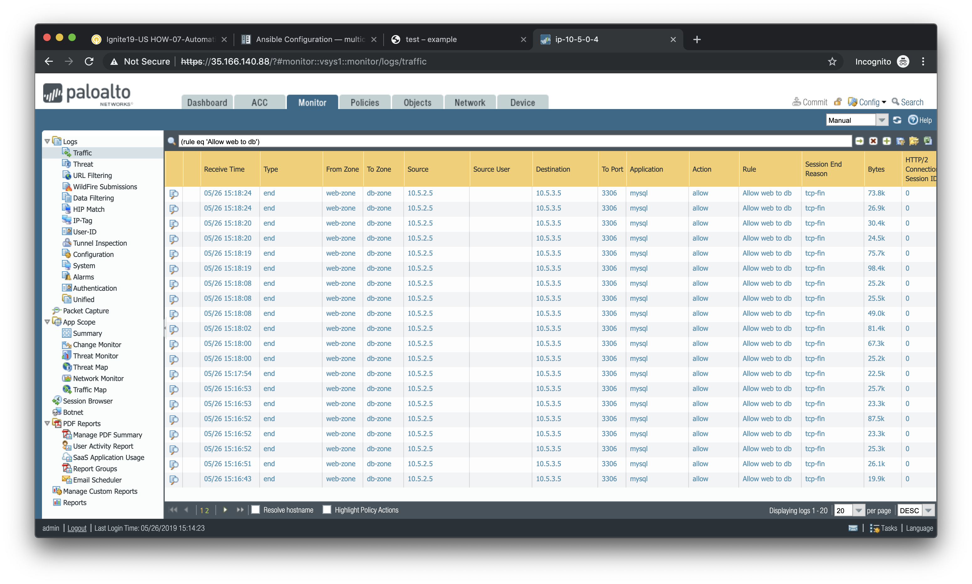
You will see all of the MySQL (actually MariaDB) database traffic between the WordPress web server and the database backend.