Respond
Respond with Palo Alto Networks
Monitor
In this activity you will:
- Create a VM Information Source (AWS)
- Verify cloud API connectivity
The automation tasks we’ve accomplished thus far have focused on deploying the VM-Series firewall and making changes to it externally via the API. We’ll now shift our focus to how PAN-OS can leverage third-party APIs to monitor its environment and automatically respond to changes it observes.
Create a VM Information Source (AWS)
We will be creating a VM Information Source on the firewall to monitor the AWS EC2 environment for meta-data about the running VM instances. Open a web browser and go to https://<your-firewall-ip>. You will log in with the following credentials.
- Username:
admin - Password:
PaloAlto2005
Once you have logged into the firewall, go to the VM Information Sources under the Device tab and click Add.
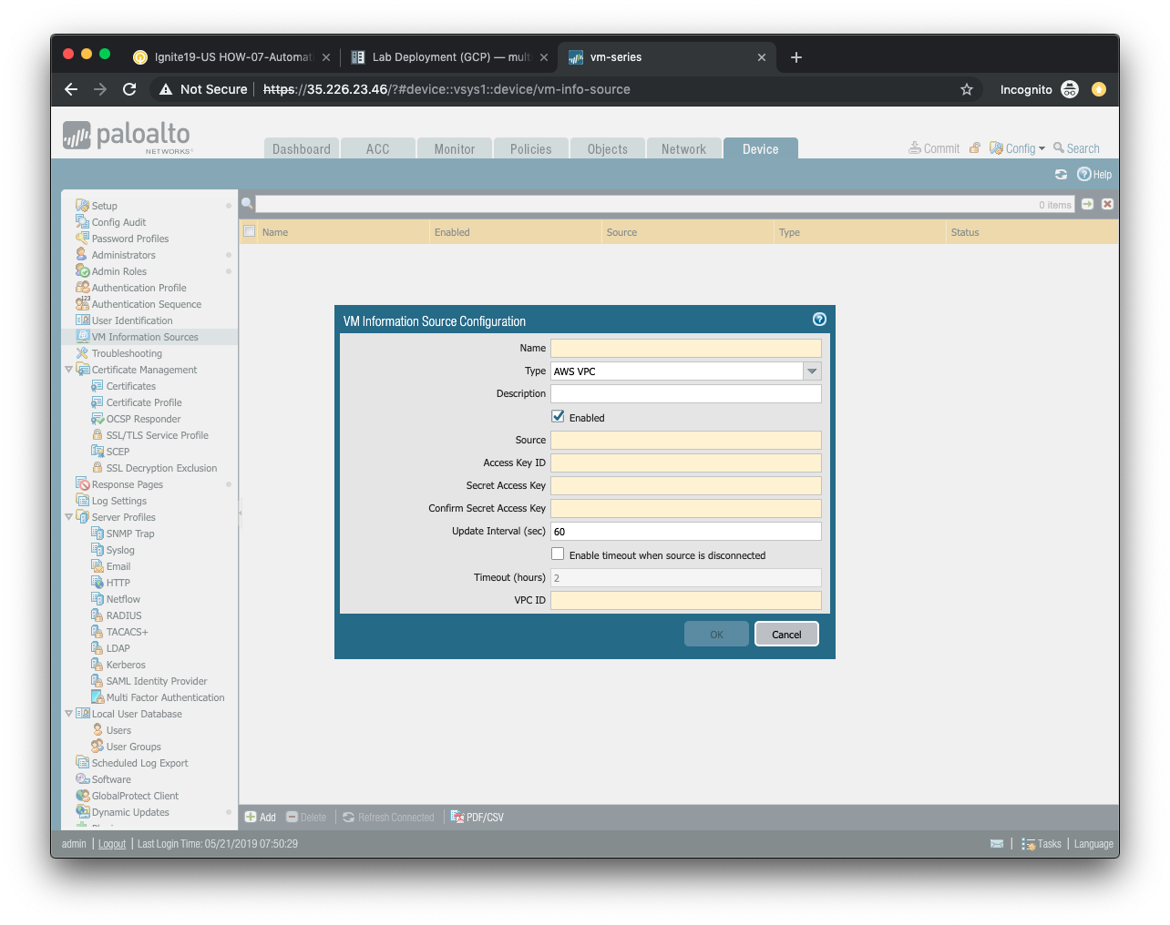
- Provide a name for your monitored source in the
Namefield. - (optional) Provide a description of the monitored source in the
Descriptionfield. - Ensure that
AWS VPCis selected from theTypefield selection. - Ensure that the
Enabledbutton is selected. - The
Sourcefield will contain the URI of the AWS region in which the lab is deployed. The format for this is ec2.<your_AWS_region>.amazonaws.com. For example, if the region is us-east-1 then the URI will beec2.us-east-1.amazonaws.com. - The Access Key ID Type
env | grep AWS_ACCESS | cut -f2 -d "="to display your key ID in the terminal. - The Secret Access Key Type
env | grep AWS_SECRET | cut -f2 -d "="to display your secret key in the terminal. - The Update Interval, and timeout fields can keep their default values.
- The VPC ID field will contain the AWS VPC value that was output during the deployment phase. You can change into the AWS deployment directory and display the Terraform output values with the following commands.
cd ~/utd-automation/journey/deployment/aws
terraform output
Click OK to accept the configuration.
Verify cloud API connectivity
Click Commit and commit the candidate configuration.
If the VM Information Source configuration was correct, you should see the status indicator for your source turn green.

If the status indicator is green, you can proceed to the next section.
DAG
In this activity you will:
- Create a Dynamic Address Group
- Define the attribute match criteria
- Apply the Dynamic Address Group to a rule
Dynamic Address Groups are policy object groups whose members are ephemeral in nature. IP addresses are dynamically mapped to a Dynamic Address Group based on attribute match criteria. These attributes are discovered from instances deployed in cloud environments and learned via cloud provider APIs.
Create a Dynamic Address Group
Navigate to Objects > Address Groups in the firewall web interface.
Click Add to create a new Dynamic Address Group.
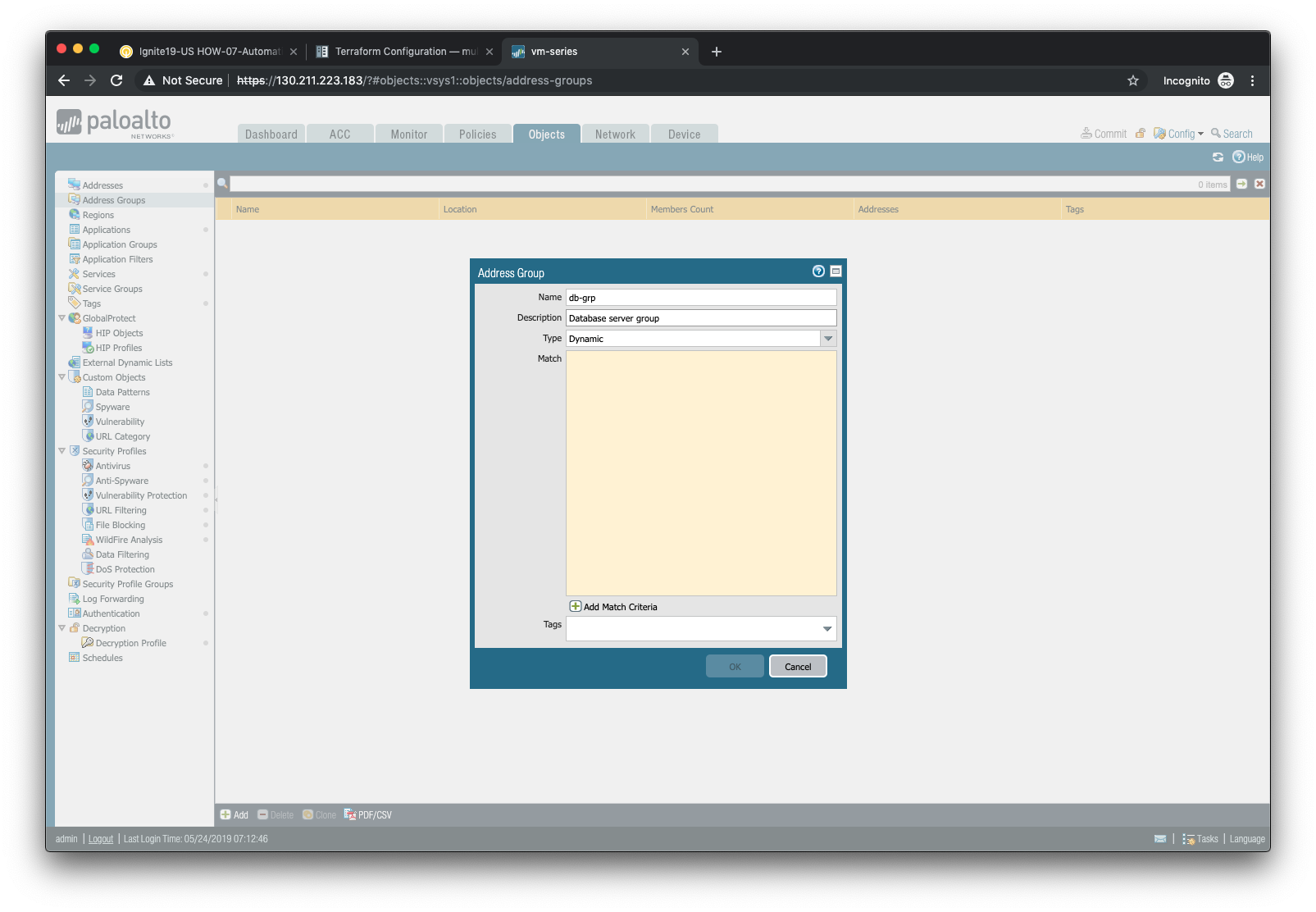
In the Address Group window:
- Assign the name
db-grpto the address groups. - (optional) Provide a description of the address group.
- Select Dynamic from the Type drop-down menu.
- Click on Add Match Criteria to view the available attributes.
Define the attribute match criteria
The attributes displayed are discovered from the cloud provider API and are refreshed every 60 seconds. You will select the attributes that will need to be matched in order to associate a VM instance to your Dynamic Address Group.
Most of the attributes displayed are not needed. However, each of the VM instances we’ve deployed have used a tag entitled server-type. Using the search bar at the top of the match criteria pop-up window, search for the term server-type. Then add the result that has a value of database to the match criteria list.
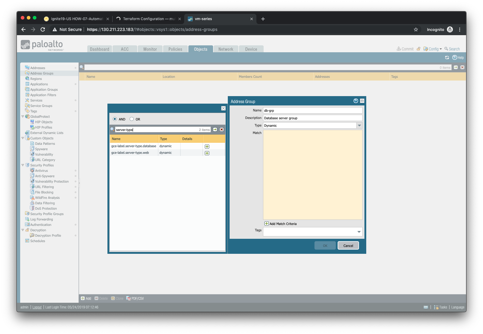
Click OK when you are done.
Apply the Dynamic Address Group to a rule
Now that we’ve defined a VM Information Source and a Dynamic Address Group, let’s put them to use. Navigate to Policies > Security in the firewall web interface.
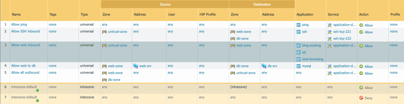
Find the rule that allows mysql traffic from the web-srv address object in the web-zone to the db-srv address object in the db-zone.
Replace the db-srv destination with the db-grp Dynamic Address Group you’ve created.
Click OK and then commit your changes by clicking Commit.
Scale
In this activity you will:
- Determine Dynamic Address Group membership
- Scale out the database instances
- Confirm Dynamic Address Group changes
The combination of VM Information Sources and Dynamic Address Groups allows the firewall to respond to changes made to the cloud environment. In this lab scenario you will scale out the number of database instances used to support the web application. This should result in the automatic update of the Dynamic Address Group membership.
Determine Dynamic Address Group membership
First, we should confirm that the one database instance we’ve already deployed has already been mapped to the Dynamic Address Group based on it’s server-type attribute.
Navigate to Objects > Address Groups in the firewall web interface and select the Dynamic Address Group db-grp that you previously created.
Under the Addresses column, click on the link entitled more...
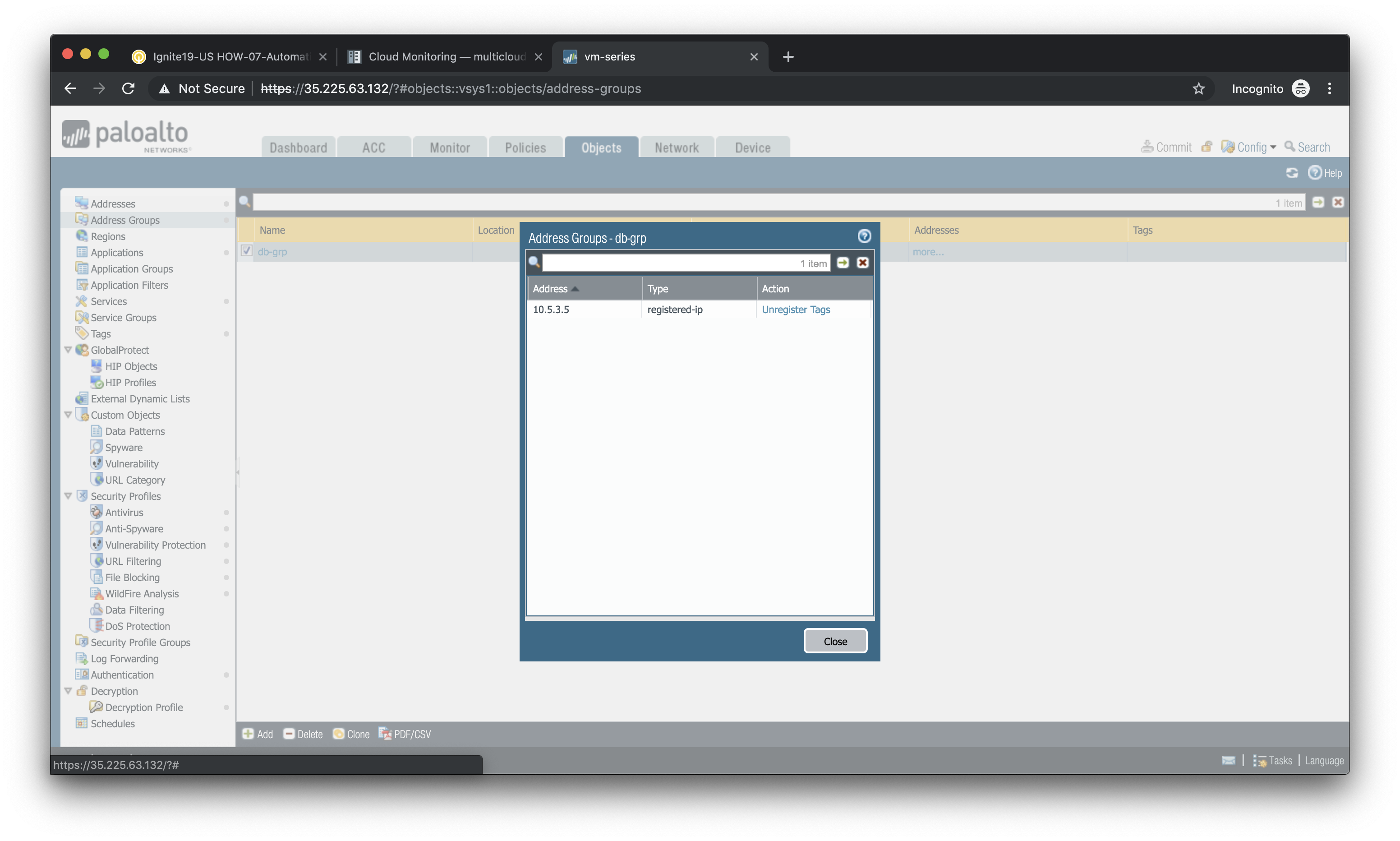
You should see the IP address 10.5.3.5, which is the IP address of the existing database instance.
Click Close to close the pop-up window.
Scale out the database instances
To scale out the number of database instances we’ll go back to our Terraform deployment.
cd ~/utd-automation/journey/deployment/aws
In the main.tf file there is a module called scale that is commented out. Open main.tf in a text editor and uncomment that entire section.
code main.tf
Do not forget to save the file (CTRL+S).
By uncommenting the scale module you have just added a new module to the Terraform plan. This will require a re-initialization of the plan.
terraform init
Then plan again:
terraform plan
You can now apply the Terraform plan.
terraform apply
This will result in four new database instances being added to the database subnet.
Confirm Dynamic Address Group changes
Now go back to the Objects > Address Groups section of the firewall web interface and click more... under the Addresses column of the db-grp entry.
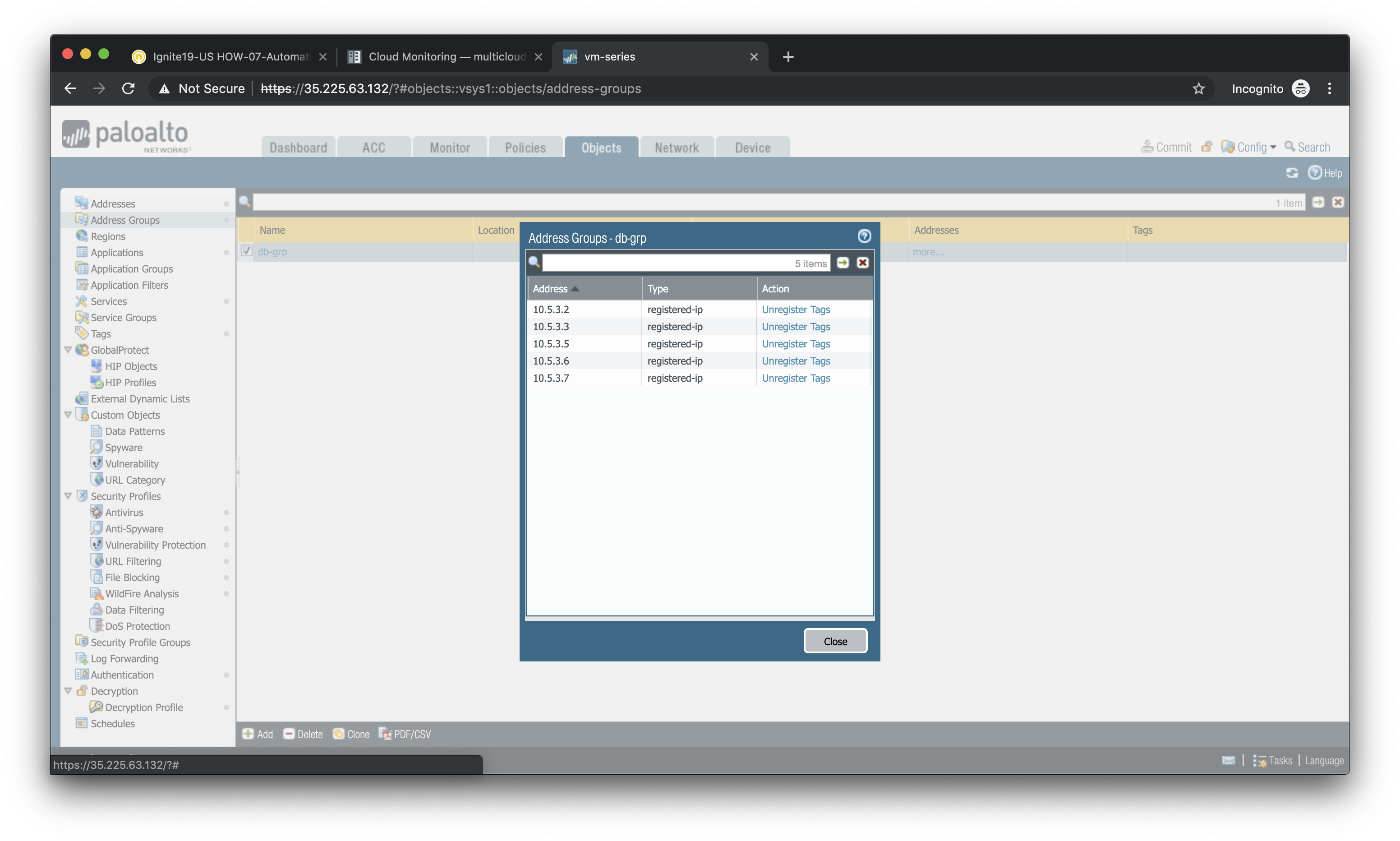
You should now see a total of five IP addresses as members of the db-grp Dynamic Address Group. These are now part of the destination match criteria for the databaase security rule.
Note
Remember that the VM Information Source is polling the cloud provider API every 60 seconds. If you do not see a total of five IP addresses in the Dynamic Address Group, close the window and click on more... again after a few moments.